- Home
- PRODUCT CENTER
- ABOUT US
- BLOG
- Application
- FAQ
- CATALOGUE
- Contact Us
Hydraulic center frame bearings are tiny components that carry a lot of weight. They are commonly incorporated into steady, self-centered rests. These bearings assist CNC lathes in meeting customer requirements for surface finish and dimensional accuracy. They also control vibration and support long, thin workpieces. Chatter increases, tool life shortens, and whole batches of parts may need to be scrapped when these bearings fail. The impact goes far beyond a single assembly.
Nonetheless, in many shops, spindle bearings are given more consideration than steady rest bearings. Operators may clamp raw stock, disregard alignment, or guess at the clamping pressure. Working with the workpiece directly without rough turning is still one of the most frequent problems on site, even though it has been shown that the straightforward solution of “rough turning first, then using a steady rest” greatly reduces damage to hydraulic center frame bearings.
This article combines:
The goal is practical: give you a complete, shop-ready framework for preventing, diagnosing, and correcting steady rest bearing problems.

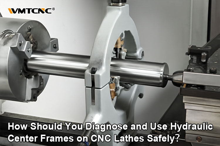
The unsupported length between the chuck and free end functions as a flexible beam when the workpiece is long relative to its diameter. When exposed to cutting or centrifugal forces, this has a tendency to deflect, “whip,” and vibrate. A hydraulic steady rest, also known as a hydraulic center frame, can help with this problem. It is made up of three rollers or bearings that clamp the workpiece at 120° intervals to keep it aligned with the spindle axis.
The advantages include:
All of these advantages, though, are contingent upon the stability of the steady rest bearings. The bearings will no longer support the bar smoothly if they are dented, contaminated, or misaligned; instead, they will become sources of error and vibration.
On the shop floor, shortcuts are frequently taken due to time constraints. Clamping a raw blank directly into the hydraulic steady rest without first forming a sanitized, circular support area is among the worst examples.
The rule is straightforward: a steady rest after rough turning successfully fixes the common problem of using the workpiece immediately without rough turning.
The article’s remaining sections describe the reasons behind the effectiveness of this advice as well as how to put it into practice with careful procedures and upkeep methods.

Bearings can sustain damage from clamping an as-received bar or forging directly in the steady rest in three ways: hard spot impact, uneven load, and increased vibration.
Mill scale, casting skin, small pits, or localized protrusions are often visible on the outside of a blank. These irregular features are much harder and rougher than a machined surface. When they come into contact with the steady rest rollers, they suffer from high localized stress.
By directly striking the rolling components of the steady rest bearing, these hard spots have an instantaneous effect, degrading the smoothness of the bearing raceways. The localized dents turn into pitting and brinelling over thousands of revolutions. Even at low speeds, the bearing starts to vibrate and rumble, and it quickly turns from a suppressor to a source of chatter.

If the outer diameter (OD) of the blank is not perfectly round, the load is not distributed evenly by the three steady rest support points. One jaw may support the majority of the radial load, while the other hardly touches the surface.
As a result of the irregularity of the blank’s outer diameter, the three steady rest support points encounter uneven loads. Long-term exposure to high loads can drastically reduce some bearings’ fatigue life.
Rolling elements and cages in the overloaded bearing deteriorate quickly in such circumstances. The overloaded bearing eventually fails due to spalling or cage fracture, runs hotter, and loses lubricant performance. This is a clear illustration of overloading, which has been found to be a common cause of bearing failure in numerous applications.
Additionally, an uneven blank surface leaves tiny spaces between the workpiece and the steady rest. These gaps transform rotational motion into shock and sporadic contact during machining. As the workpiece oscillates, the steady rest bearings go through a state known as “alternating impact,” where they make contact, separate, and then impact once more. Vibration at a high frequency that is transmitted to the workpiece, tool, and spindle.
This reduces machining precision and speeds up bearing damage from false brinelling and fretting, particularly if the machine is vibrated by the environment even when it is not moving.
A comprehensive operating procedure for hydraulic center frames on CNC or horizontal lathes is also covered in the required material. You can create a strong standard operating procedure by converting that into an organized process.

Start by giving the bar surface near the support band and the support jaws a thorough cleaning:
Take out the oil, dried coolant, and iron filings.
Make sure there are no abrasive particles stuck between the workpiece and the jaws.
Maintaining cleanliness lowers the chance of contamination getting into the bearings and shields the workpiece’s surface from harm.
Then, based on the bar’s diameter and geometry, choose and install the proper support jaws (curved jaws for round bars, for example).
To ensure that the steady rest is coaxial with the machine spindle axis, first align the centers of the three jaws using the adjustment screws. This misalignment will pull the shaft off center, resulting in load imbalance and taper.
Turn on the hydraulic station.
Adjust the system pressure to the necessary clamping value.
For large-diameter, hard bars, slightly increase the pressure to avoid slippage.
For soft or thin-wall materials, lower the pressure to prevent plastic deformation.
Using the control panel, set the clamping stroke such that the jaws make full contact with the workpiece without compressing it too much. To increase repeatability, some contemporary machines have pressure feedback and shut off automatically when the predetermined pressure is reached.
With the hydraulic system configured:
If abnormalities appear, fine-tune clamping pressure or pause machining to inspect jaw contact.
After machining:

All three jaws must move in unison for stable rest performance. The bar will be displaced off-center by any jamming, lag, or uneven feed, increasing runout and leading to machining errors.
If you observe asymmetrical jaw closing or feel resistance, check:
Clamping pressure mismatch is a frequent root cause of both part defects and bearing damage:
Too low pressure → bar slips, surface finish deteriorates, and bearings experience shock loads.
Too high pressure → the bar—especially aluminum, copper, or thin-wall tubing—experiences plastic deformation and may “egg shape,” which again leads to uneven bearing loading.
The best practice is to perform trial clamping for each new material/diameter combination, then document the optimal pressure settings so operators do not have to guess.
Support location is another critical variable. As a rule of thumb, the center frame should be positioned 300–500 mm away from the machining area.
Too close to the tool: cutting forces are transmitted directly to the steady rest and its bearings, increasing vibration and wear.
Too far from the tool: the cantilever length grows, deflection increases, and the bar begins to whip.
Adjust this range based on part geometry and cutting conditions, but always think in terms of minimizing both deflection and transmitted shock.
Numerous recurrent problems are highlighted in the general literature on bearing problems, including excessive noise, vibration, overheating, premature wear, corrosion, incorrect installation, and lubrication faults.
Symptoms:
Unusual noise (grinding, clicking, humming).
Increased vibration detected by feel, sensors, or surface finish.
Runout spikes near the steady rest.
Potential causes:
Hard spot damage from direct blank clamping.
Misalignment between steady rest and spindle.
Looseness in mounting or worn rolling elements.
Corrective actions:
Reinforce the rule of rough turning a support band before clamping.
Re-align steady rest, verifying coaxiality with the spindle.
Replace bearings that feel rough when rotated by hand.
Symptoms:
Bearing housings warm or hot to the touch.
Discolored or burnt lubricant.
Elevated temperature readings from IR thermometers.
Potential causes:
Inadequate or wrong lubricant type; insufficient or excessive quantity.
Overloaded bearings from excessive clamping pressure.
Contamination (chips, dust, coolant) breaking down the lubricant film.
Corrective actions:
Follow manufacturer guidelines for lubricant type, quantity, and relubrication interval.
Adjust clamping pressure; ensure proper load sharing among jaws.
Improve sealing and cleanliness around the steady rest area.

Preventing the underlying causes of failure, particularly contamination and lubrication, is the main goal of proactive maintenance.
Key principles:
Implement a scheduled lubrication regimen that matches real operating conditions.
Use correct lubricants with suitable viscosity and additive packages.
Install effective seals and shields to keep out dust, chips, and coolant.
Keep the area around steady rests clean; avoid directing high-pressure coolant directly at seals.
You can track bearing health and transition from reactive repairs to predictive maintenance with the help of contemporary condition monitoring techniques like vibration analysis, temperature trending, and lubricant analysis.
For steady rest and spindle bearings, this can include:
When trends show deterioration, you can schedule maintenance during planned downtime rather than reacting to unexpected breakdowns.
The table below compares clamping a raw blank directly in the steady rest versus applying a “rough turning first, then using a steady rest” strategy.
| Aspect | Direct Blank Clamping | Rough-Turned Support Area |
|---|---|---|
| Surface under bearings | Scale, pits, localized protrusions | Smooth machined band 50–100 mm long |
| Load distribution on three jaws | Uneven; one jaw often overloaded | Balanced; jaws share load more uniformly |
| Bearing contact state | Alternating impact and shock | Steady rolling contact |
| Vibration and chatter | Higher; unstable, prone to chatter | Lower; improved dynamic stiffness |
| Risk of workpiece deformation | High for soft or thin-wall stock | Lower thanks to controlled pressure and better fit |
| Expected bearing life | Short; premature wear and spalling | Longer; significantly reduced damage rate |
| Surface finish near support | Rings, chatter marks, potential burnishing | Stable finish with minimal support marks |
| Setup and downtime | Slightly quicker setup, but more unplanned downtime | Slightly longer setup, but fewer breakdowns overall |
The increased stability, decreased rework, and longer bearing life more than make up for the additional operation that rough turning adds. When steady rest bearings replace frequent failure points and become dependable and predictable, the overall cost of ownership of a CNC lathe decreases over time.

On CNC lathes, hydraulic center frame bearings are located where mechanical dependability and machining process meet. They become persistent sources of noise, vibration, subpar finish, and unplanned downtime when they are clamped directly onto raw blanks and handled like consumables.
By contrast, when shops embrace the practices described here—
…hydraulic center frames transform from a weak link into a robust asset. CNC lathes provide the performance, accuracy, and uptime that competitive manufacturing requires, and bearing failures cease to be frequent annoyances.
Operators benefit from clear CNC turning best practices—covering setup, machining tips, and safety—to support CNC turning operations suppliers in delivering consistent, accurate, and high-quality production.>> Read more
CNC automation leverages digital control to streamline machining for precision, speed, and cost-efficiency. By replacing manual input with CAD/CAM-driven G-code, modern CNC systems drive consistent, high-volume production.>> Read more
Slant-bed CNC lathes offer enhanced rigidity, chip removal, and precision. With 30°, 45°, and 60° bed options tailored for small parts, versatile machining, or heavy-duty tasks, they outperform flat-bed models in stability and efficiency.>> Read more
Shaper machines utilize a reciprocating single-point cutter to shape flat surfaces, grooves, and profiles. Available in crank, hydraulic, vertical, universal, and traveling-head types, they excel in heavy-duty, precise, short-run tasks and are increasingly adapted with CNC retrofits.>> Read more
Lathe chucks ensure secure, precise clamping on a lathe spindle. They include types like 3-jaw, 4-jaw, magnetic, collet, and powered variants to suit varied materials and machining needs.>> Read more


Tags: CNC Lathe, Hydraulic Center Frame