- Home
- PRODUCT CENTER
- ABOUT US
- BLOG
- Application
- FAQ
- CATALOGUE
- Contact Us
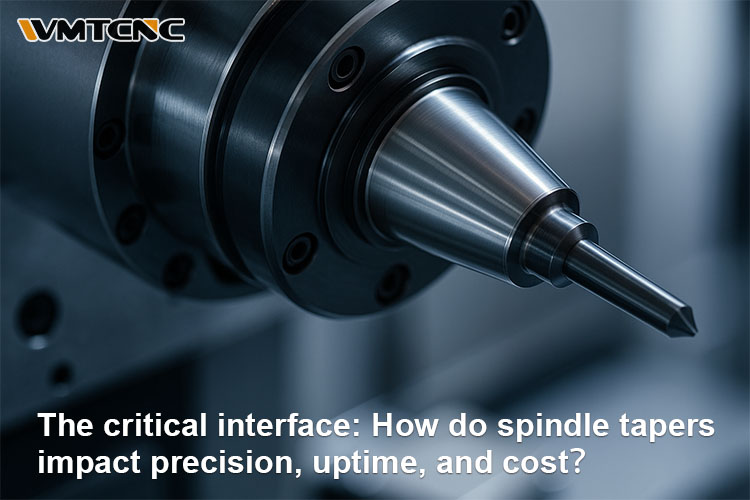
A taper is a gradual reduction in the diameter of a part, typically forming a conical profile. In machining, this geometry is used to locate and clamp tool holders with high repeatability. Because the surfaces meet over an area—not at a point—the taper can support substantial radial and axial loads while maintaining concentricity. The geometry also self-centers the tool holder in the spindle, which directly influences runout, surface finish, and tool life. Even a few microns of angular error or contamination at this interface can multiply into visible surface waviness, poor size control, and premature tool wear.

A spindle taper is the precision-ground conical seat inside a machine tool’s spindle. A matching male taper on the tool holder is inserted into the spindle’s female taper. In drawbar-retained systems (e.g., CAT/BT), a retention knob or mechanism applies axial force to seat the holder firmly. In self-holding systems (e.g., Morse), the friction generated by the interference fit alone locks the holder in place for light-to-medium duty. When the interface is clean, undamaged, and properly aligned, the tool is centered and stable; if it is dirty, bruised, or misaligned, you will see poor tool performance, increased chatter, and a drop in machining accuracy.
The taper’s first job is to securely clamp the tool holder, transmit spindle torque, and resist deflection under cutting loads. By maximizing contact area and friction, the taper reduces micro-slip that would otherwise cause chatter, heat, and fretting corrosion. This stability shows up as improved dimensional control, tighter roundness and straightness, and a cleaner surface finish.

Modern production depends on quick, repeatable tool changes. With a well-maintained taper interface, tools enter and seat consistently at the same gage line. That repeatability allows you to clamp shorter stick-outs, run higher radial engagement, and schedule predictable tool life—all of which drives throughput and OEE (Overall Equipment Effectiveness).
Developed in the 19th century and still common today, Morse tapers (MT0–MT7) are ubiquitous on drill presses and lathes. Their self-holding behavior is convenient for rapid manual setups. They shine in light–medium duty work and as lathe tailstock tapers for centers and drills. Because clamping force comes from the interference fit itself, Morse is typically not the first choice for high-torque milling or aggressive metal removal.

CAT (V-flange) and BT holders are the mainstays of vertical and horizontal machining centers. Both use drawbar retention, which applies consistent force via retention knobs (pull studs). CAT is common in North America; BT has a symmetric flange that balances well for automatic tool changers. Sizes (30/40/50) correlate with shank stiffness and torque capacity. Choose CAT/BT when you prioritize robust clamping for roughing, slotting, and heavy chip loads.
The R8 system (Bridgeport) relies on a drawbar to pull the collet/toolholder into a short taper. It’s simple, economical, and still common in toolrooms and job shops with knee mills. While not as rigid as CAT/BT. R8 remains practical for moderate cutting and prototype work.

Start by confirming the spindle nose standard and the retention style the machine supports. Milling centers typically use CAT or BT. Lathes and drill presses commonly use Morse. For knee mills and lighter work, R8 is prevalent. Mis-matching tapers risks tool pull-out, drawbar damage, and poor alignment.
Tie taper selection to tolerance and finish targets. If your prints call for ≤ 5 µm TIR at the gage line, and you routinely finish at high rpm, HSK or premium balanced CAT/BT holders are appropriate. For heavy roughing in steels and high-MRR slotting, leverage the torque capacity of CAT/BT 40/50. Consider the tool length and gage line—longer overhangs magnify deflection; rigid holders (shrink-fit, hydraulic) and stubbier gage lengths mitigate chatter.

A clean, healthy taper is the difference between a confident process and an unpredictable one.
Daily: Wipe the spindle bore and tool tapers with lint-free cloths; avoid handling tapers with oily hands.
Per shift: Inspect for fretting marks (dark smudges), dings, or raised metal; check for chips.
Weekly: Perform a quick blue-check for contact area and verify pull-stud torque.
Monthly: Indicate TIR at the gage line with a qualified test bar; typical finishing targets are ≤ 0.005–0.010 mm.
Quarterly: Check drawbar force, gripper fingers, keys, and balance.
Proactive upkeep avoids the hidden cost of poor finishes, unexpected tool breakage, and rework.
Chatter on entry or exit: Look for burrs, embedded chips, or glazed areas on the taper; stone lightly with a fine slip, clean, and reseat.
Poor circularity/finish: Verify holder runout and spindle TIR separately; swap holders to isolate the source.
Tool pull-out: Confirm correct pull-stud geometry and torque; test drawbar force against OEM specs.
Heat and noise: Persistent heating may indicate bearing preload or misalignment problems—schedule service before damage propagates.
If repeatability disappears despite clean interfaces, or if TIR remains high across multiple holders, a taper regrind may be required. Professional service providers use air gauging, cylindrical grinding, and dynamic balancing to restore geometry. Severe cases (brinelling, bell-mouthing, spindle bearing wear) call for a rebuild and machine alignment verification.

Spindle tapers are small components with outsized influence on accuracy, throughput, and cost per part. Choosing the correct taper for your machine and application—and keeping that interface clean, undamaged, and aligned—is the surest way to protect tool life, reduce chatter, and hit demanding tolerances. When performance drifts, inspect the taper first: it’s often the quickest, least expensive fix to restore process capability.
BT tapers (BT30/40/50) offer symmetric design for high rigidity and compatibility with autocheckers; SK tapers follow DIN 69871, excel in concentricity and high-speed stability—choose based on machining needs and regional support.>> Read more
Lathe chucks ensure secure, precise clamping on a lathe spindle. They include types like 3-jaw, 4-jaw, magnetic, collet, and powered variants to suit varied materials and machining needs.>> Read more
CNC spindles are vital for machining functions like drilling, milling, and cutting, with diverse structural designs tailored for precision and application-specific performance.>> Read more
DC motors offer precise speed and high starting torque for robotics and EVs but need maintenance. AC motors are rugged, low-cost, with long lifespan—ideal for HVAC, industrial machinery, and appliances.>> Read more
Shaper machines utilize a reciprocating single-point cutter to shape flat surfaces, grooves, and profiles. Available in crank, hydraulic, vertical, universal, and traveling-head types, they excel in heavy-duty, precise, short-run tasks and are increasingly adapted with CNC retrofits.>> Read more


Tags: Spindle Tapers, Spindles